Loose or displaced material
Promptly review detached sealant, covers, tiles, render, masonry or metalwork where material could fall or a joint edge has moved out of plane. Do not pull on loose components to test them.

Split sealant, open edges, recurrent leakage, stained finishes and separation at a slab, wall, parapet, balcony or façade junction are conditions to investigate—not instructions to apply another bead of sealant. A reliable plan connects the visible joint to the movement it must accommodate, the substrates it bonds to, the waterproofing and weathering layers it intersects, and the occupied areas around the work.
This guide helps NSW owners corporations, asset managers and property teams prepare an evidence-led expansion-joint repair brief. It supports SCE's building remedial services but does not replace engineering, façade, waterproofing, product, access, approval or safety advice. For work extending beyond the joint, coordinate the structural, waterproofing and façade requirements within the wider repair scope.
Map the complete joint before selecting the repair. A joint is a moving interface, not merely a line of sealant. Record its geometry, terminations, transitions and connected layers before the visible material is removed.
A failed or displaced joint can coincide with loose finishes, water entry, exposed edges or movement of adjoining construction. The appearance of the sealant alone cannot establish the risk. The responsible duty holders should consider change, location and exposure before arranging routine repair pricing.
Promptly review detached sealant, covers, tiles, render, masonry or metalwork where material could fall or a joint edge has moved out of plane. Do not pull on loose components to test them.
Protect affected people, finishes, electrical services and occupied areas. Record the weather, water path and joint condition before temporary measures obscure useful evidence.
Sudden opening, closing, shearing or displacement after impact, nearby works, structural change or severe weather warrants competent site-specific review before the joint is disturbed.
Temporary sealing is not the permanent design. If an interim measure is needed, document its limits, compatibility and removal requirements so it does not conceal change or compromise the final substrate.
Record each condition from a stable reference and inspect the connected construction where safe and accessible. Similar-looking failures can result from different combinations of geometry, movement, adhesion, preparation, moisture, ageing and interface detailing.
| Observed condition | Questions to investigate | Scope risk if assumed |
|---|---|---|
| Sealant pulls away from one edge | Was the adhesion face sound, clean, dry and primed where required? Is the substrate compatible? Is the joint cycling, twisting or moving beyond the installed profile? | Another bead may bond to residue or a weak coating and repeat the adhesive failure. |
| Sealant tears through its body | What was the installed width and depth? Was backing or a bond breaker present? What movement occurred and what capacity was actually designed? | A stronger or stiffer material may transfer stress to the edges without correcting the geometry. |
| Joint is closed, compressed or extruded | Is the opening at one end of its movement cycle? Are covers, backing or debris restricting compression? Have adjoining elements displaced? | Cutting out material at the wrong condition can leave insufficient width when the assembly moves again. |
| Leakage near a joint or termination | Where is the drainage surface and membrane? How do the joint, upturns, flashings, hobs, thresholds and façade systems connect? Is the visible joint actually the entry point? | Surface sealing can redirect water or leave a concealed membrane discontinuity untreated. |
| Repeated patching or mixed sealants | What products and primers were used, where do they start and stop, and are they compatible with each other and the substrates? Why did the prior work fail? | Partial removal can retain incompatible material and create irregular movement or adhesion zones. |
| Cracking beside, rather than in, the joint | Is movement being transferred into render, screed, tiles, masonry or cladding? Does the joint align through the assembly? Are restraints or rigid finishes bridging it? | Repairing the crack while leaving a bridged or discontinuous movement path may move the failure line. |
Do not infer performance from appearance alone. A clean joint can still have inadequate depth, backing, adhesion or hidden continuity. A weathered joint may remain serviceable. The required evidence depends on the building, exposure, consequence and repair objective.
A joint register turns disconnected photographs and maintenance notes into an auditable scope. It should use identifiers that remain stable through investigation, design, pricing, construction and handover.
Photograph the full route as well as close details. Include a scale and joint identifier, but do not place hands, tools or loose objects in an unsafe area simply to obtain a measurement. Use the access system and competent people appropriate to the location.
The sequence can be compressed for a small, low-risk maintenance task or expanded for a regulated, high-access project. Each stage should still create a traceable decision or information set.
Assign stable references and document its complete route, condition, intersections, terminations and affected spaces. Separate an isolated sealant joint from a structural movement joint or proprietary cover system.
Have the responsible team decide on exclusion, temporary protection, weatherproofing, support, monitoring or urgent specialist review. Record what an interim measure can and cannot achieve.
Use targeted opening-up, measurements, product review, survey, moisture investigation or testing to answer defined questions. SCE's visual and intrusive investigation guide explains how to convert unknowns into controlled investigation tasks.
The appointed practitioners should define the required movement range, joint configuration, substrate preparation, system components, terminations, transitions, drainage and acceptance criteria for the actual assembly.
Where specified, complete a sample or trial that demonstrates removal, edge preparation, backing, primer, sealant or cover installation, finish and testing. Record ambient and substrate conditions.
Sequence complete joint lengths or designed termination points. Coordinate scaffold, elevated work platforms or other access; resident restrictions; plant; traffic; weather windows; daily closure and emergency routes.
Stop at nominated stages for review of prepared edges, measured dimensions, backing or bond breaker, primer, membrane transitions, cover fixings and completed profiles. Resolve departures before repeating them.
Index products, batches, photographs, measurements, inspections, test results, design changes, as-built details and warranties to the joint register. Define maintenance and future inspection responsibilities.
Selection should follow the movement and interface requirements, not the other way around. A data sheet is evidence about a product under stated conditions; it is not a project-specific joint design.
Confirm the intended joint type, movement range and direction, installed opening across relevant conditions, required width-to-depth profile, backing or bond-breaker arrangement, tolerances and whether a proprietary cover is part of the system.
Identify concrete, masonry, metal, membrane, coating, render, tile, stone or other adhesion faces. Define removal of old materials, edge repair, dryness, cleaning, primer, compatibility and minimum acceptable substrate condition.
Map the drainage plane, membrane continuity, flashings, cavities, weeps, falls, hobs, thresholds and terminations. The repair should shed or control water without blocking drainage or creating a concealed reservoir.
A joint may also form part of a fire-resisting, acoustic, vehicular, pedestrian or contamination-control assembly. Do not substitute a generic sealant where the joint has another required performance or certification pathway.
Agree colour, texture, edge lines, masking, tooling and acceptable appearance while preserving performance. Provide practical inspection and replacement access rather than burying a maintainable joint behind rigid finishes.
Nominate trials, substrate checks, adhesion or pull testing, joint measurements, environmental limits, water testing where appropriate, inspection hold points and the records needed to demonstrate the installed system.
NCC 2022 Volume One Part F1 addresses exposed construction, control, expansion, contraction and movement joints on roofs, balconies, podiums and similar horizontal surfaces. The project team must establish the applicable NCC edition, state variations, building classification, referenced standards and approval path for the actual work. This guide does not reproduce or replace those requirements.
Where structural movement or distress is genuinely in question, route the matter to the existing structural remedial services pathway and the appointed engineer to establish the investigation and repair approach.
Joint work often follows long elevations, roof edges, balconies, podiums, car parks or internal separations. The access method affects what can be inspected, how removal is controlled, what length can be completed, and how the building remains weatherproof and safe between shifts.
SafeWork NSW requires fall risks to be managed at any height, with additional construction-work requirements where a person could fall more than two metres. The project PCBU and duty holders must prepare and implement the site-specific controls required by the actual work.
| Role | Typical responsibility | Control question |
|---|---|---|
| Owner or owners corporation | Authorise investigation, access, appointments, budget, staging decisions and resident or tenant communication. | Who can approve temporary controls, design changes, variations and release of affected areas? |
| Structural, façade and waterproofing designers | Assess matters within their competence and define movement, interfaces, details, regulated documents and acceptance criteria. | Who owns the joint across structure, enclosure, membrane, finishes and every termination? |
| Product or system technical representative | Provide current documented limitations, compatibility, preparation, installation and test information for the specified system. | Has advice been reconciled with the project design rather than treated as the design? |
| Building practitioner and remedial contractor | Plan and construct the authorised scope with safe access, temporary weathering, substrate preparation, quality records and notifications. | What condition requires work to stop before installation or concealment continues? |
| Superintendent, certifier or independent reviewer | Perform the stated contractual, statutory or assurance function and review nominated evidence. | What constitutes acceptance, and who signs each hold point and final register? |
For class 2 work, SCE's DBP remedial works guide provides a focused planning pathway. The appointed registered practitioners must determine the regulated design, declaration and Planning Portal obligations for the actual building and scope.
SCE completed an approved five-item scope at an occupied Surry Hills strata building: structural assessment and investigations, a building remediation specification, an engineering inspection report, remediation design and tender process management. The project page records SCE's role as contractor and project coordinator with specialist engineering consultant input.
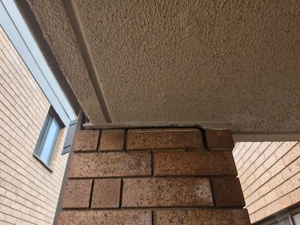
Review the completed investigation and design scope on the Surry Hills strata building investigation project page. The photograph documents an interface condition; it does not establish that the interface is an expansion joint, identify the mechanism, or prescribe a repair for another building.
Price the same information basis. Require respondents to identify assumptions, exclusions, provisional quantities, access method, prepared-edge repairs, temporary weathering, design dependencies, test requirements and record deliverables. A metre rate without a defined joint profile and substrate basis is not a complete comparison.
Use SCE's remedial planning tool to organise available information. Where the dominant issue is broader building-envelope performance, use the waterproofing and façade sealing guide to plan the connected repair work.
Confirm the joint location, construction, substrates, dimensions, condition and intended function before selecting a repair. Record movement or displacement, sealant and backing condition, adhesion faces, contamination, moisture routes, terminations, intersections, adjacent membranes, flashings, finishes and prior repairs. Review drawings and movement assumptions where available, and arrange design, testing or opening-up where the responsible practitioners need it. Keep verified facts separate from provisional conditions.
Sometimes resealing is part of the designed repair, but removing and replacing sealant is not automatically sufficient. Failure may involve unsuitable geometry, loss of adhesion, cohesive tearing, aged backing, incompatible materials, wet or contaminated substrates, excessive or unaccommodated movement, failed terminations, membrane discontinuity or movement elsewhere in the assembly. The scope should correct the relevant mechanism and specify preparation, backing, primer, sealant, profile, movement capacity and inspection requirements.
The responsible designer determines the project-specific movement range and joint configuration using the actual structure, materials, support and restraint conditions, temperature and moisture effects, construction tolerances, existing dimensions and available design information. A product movement rating does not by itself establish a suitable joint. The selected system must be compatible with the substrates and joint geometry and remain buildable across the expected range, including at changes in direction and terminations.
A joint may cross or terminate at membranes, flashings, cavity systems, cladding, render, parapets, door thresholds, drainage surfaces or other weathering elements. Repairing only the visible sealant can leave a concealed discontinuity or redirect water. The design should map these interfaces, define laps and transitions, coordinate movement and drainage, and nominate opening-up and water-testing requirements where appropriate. Exposed joints on relevant roofs, balconies and podiums also require project-specific consideration of NCC Part F1 and the referenced standards.
Yes, where the responsible team develops a safe, weather-resilient sequence for the actual site. The plan should address access, fall and falling-object controls, resident or tenant communication, noise and odour, façade or balcony restrictions, temporary weatherproofing, daily closure, emergency access, protection of finishes and services, inspection windows and release criteria. Staging boundaries should follow complete joint lengths or designed termination points rather than convenient but technically unsuitable breaks.
Agree the record set before work starts. It may include an indexed joint register, construction-issued details, approvals and declarations, substrate and preparation photographs, joint dimensions, backing and bond-breaker records, product and batch information, primer and compatibility records, environmental conditions, sample or adhesion results, hold-point sign-offs, water-test results where specified, approved changes, as-built locations, warranties, maintenance instructions and residual monitoring or inspection obligations.
Primary-source links were checked on 4 September 2026. The applicable NCC edition and state variations, referenced standards, building classification, approval pathway, work health and safety duties and practitioner obligations depend on the actual asset and scope. Confirm current project-specific requirements; referenced standards may require licensed access.
Send SCE the site address, joint register or marked drawings, dated photographs, leak and repair history, dimensions or monitoring, available design information, affected interfaces, access constraints, approval status and required programme. SCE provides investigation, engineering, remediation design, procurement and construction for complex building repairs, working with appointed specialists where required. We can establish the design and delivery scope together, including the joint's structural, waterproofing and façade interfaces, while independent certification and statutory approvals remain with the responsible practitioners and authorities.
Request a Project Suitability ReviewLast reviewed: 4 September 2026. General information only; obtain site-specific safety, structural, façade, waterproofing, fire, acoustic, product, access, planning, DBP and certification advice from the appropriate practitioners and authorities.